


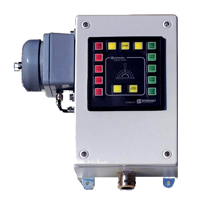

Engine Order Telegraph (EOT) and Em’cy Engine Order Telegraph Systems (EEOT)
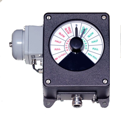
The main purpose of sm electrics‘ Engine Order Telegraph system [EOT] is to generate the desired RPM or pitch value for the connected propulsion remote control system by a sustained and reliable lever – known as well as human machine interface (HMI). In case the connected propulsion remote control system is disturbed the engine order telegraph system is in use to transfer manoeuvre commands to the engine control room or, if required, directly to the engine room‘s ME local station. The given manoevre command activates an audible alarm as long as the command has been accepted by corresponding operation at the connected participants.
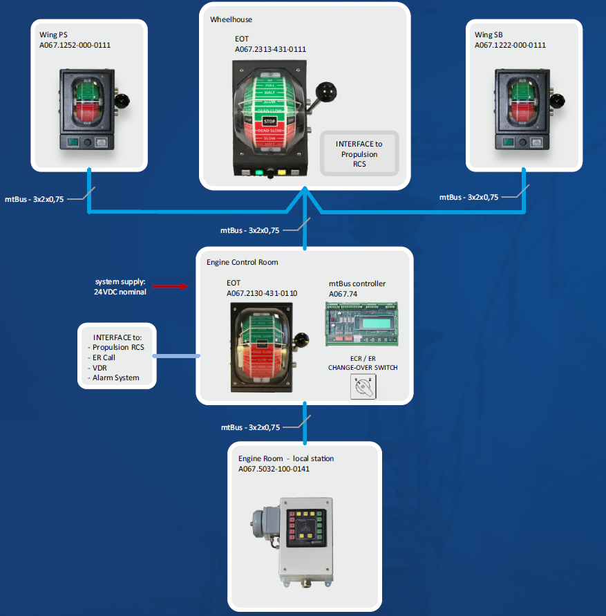
The modular system structure allows to extend the system by wing control units. All telegraphs located on the bridge e.g. bridge FWD, bridge AFT, wing SB, wing PS are connected to each other by a virtual mechanical shaft to make them work synchronously. That virtual shaft is called Electrical Shaft and oprerates as a remote control of the main bridge FWD telegraph which is providing the main interface to the connected propulsion remote control system.
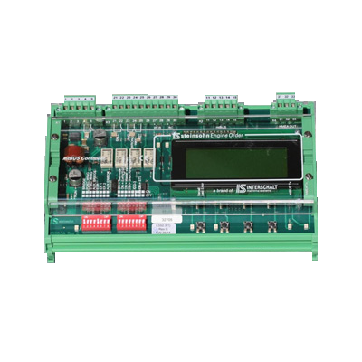
The centralized A067 mt-Bus controller, mostly located inside the engine control room console, controls and monitors all network participants and provides further interface signals for ER call, VDR and connected IAMC systems. The centralized A067 mt Bus controller, mostly located inside the engine control room console, controls and monitors all network participants and provides further interface signals for ER call, VDR and connected IAMC systems.
sm electrics’ A067 mtBUS controller is designed to manage and monitor permanently all connected network units. Simply to be mounted on a terminal rail (TS35) the controller provides useful system information to the commissioning, service and maintenance staff indicated clearly on a 4 lines 20 characters LC display.
Your benefits:
- intuitive operation
- reliable and economic mtBUS-system
- easy to install – no on-site adjustments required
- highly integrated and modular system structure
- two handle types and two EOT sizes available
- twin EOT for twin main engine control available
- clear system diagnosis via central LCDisplay
- various interface technologies to your propulsion RC system
- serial VDR interface
- type approved by all major classification societies
The main purpose of sm electrics‘ Engine Order Telegraph system [EOT] is to generate the desired RPM or pitch value for the connected propulsion remote control system by a sustained and reliable lever – known as well as human machine interface (HMI). In case the connected propulsion remote control system is disturbed the engine order telegraph system is in use to transfer manoeuvre commands to the engine control room or, if required, directly to the engine room‘s ME local station. The given manoevre command activates an audible alarm as long as the command has been accepted by corresponding operation at the connected participants.
The modular system structure allows to extend the system by wing control units. All telegraphs located on the bridge e.g. bridge FWD, bridge AFT, wing SB, wing PS are connected to each other by a virtual mechanical shaft to make them work synchronously. That virtual shaft is called Electrical Shaft and oprerates as a remote control of the main bridge FWD telegraph which is providing the main interface to the connected propulsion remote control system.
The centralized A067 mt-Bus controller, mostly located inside the engine control room console, controls and monitors all network participants and provides further interface signals for ER call, VDR and connected IAMC systems. The centralized A067 mt Bus controller, mostly located inside the engine control room console, controls and monitors all network participants and provides further interface signals for ER call, VDR and connected IAMC systems.
sm electrics’ A067 mtBUS controller is designed to manage and monitor permanently all connected network units. Simply to be mounted on a terminal rail (TS35) the controller provides useful system information to the commissioning, service and maintenance staff indicated clearly on a 4 lines 20 characters LC display.
Performance characteristics:
- well established and sustained RS485 bi-directional mtBus technology
- system voltage: 24 VDC nominal
- power consumption 2-3 W
- to be installed on TS35 terminal rail
- LC display with 20 characters in 4 lines for system diagnosis
- VDR connection baud rate selectable 4.800 to 38.400 bit/s
- Wrong way contacts (dry relay contacts)
- EOT Call alarm (dry n/o relay contact)
- Failure contact (dry n/c relay contact).